Phone:
+86 13828 600940
Physical address:
No.8Liyuan Road, Bogang community, Shajing Street Baoan District, Shenzhen, China
Phone:
+86 13828 600940
Physical address:
No.8Liyuan Road, Bogang community, Shajing Street Baoan District, Shenzhen, China

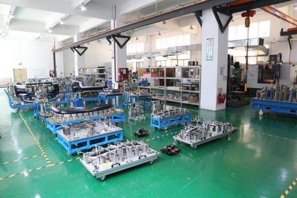
Welding fixtures are a collection of special testing equipment and tools used to evaluate the dimensional accuracy, geometric tolerance and welding quality of welded structures. Their core function is to ensure that welded parts meet design requirements and achieve quality controllability in engineering manufacturing. The shape of the gauge must be milled according to the CAD data of the part, which can reflect all the parameters of the part and perform qualitative inspection on the part. For some extremely important functional dimensions on the part, the gauge can also be used for numerical inspection. It is used to check the shape of the part, trimming lines, fold lines, and hole positions. As a bridge connecting design specifications and production practices, welding gauges integrate precision measurement technology, material mechanics analysis, and digital quality control methods, and are widely used in high-end manufacturing fields such as automobiles, aerospace, ships, and energy equipment.
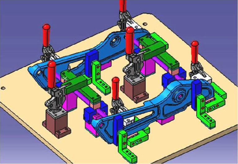
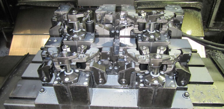
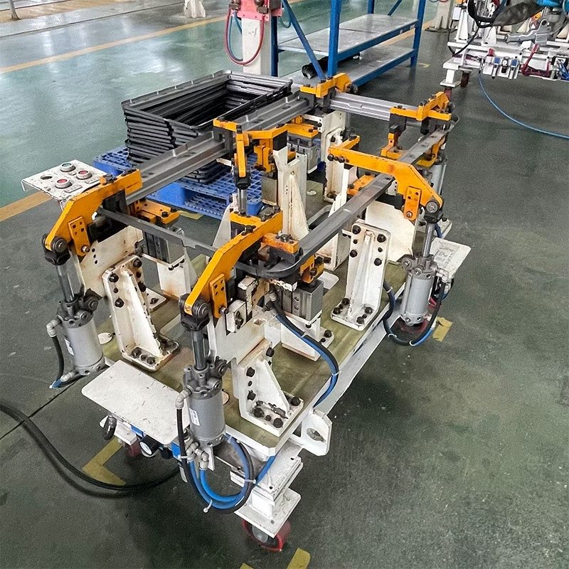
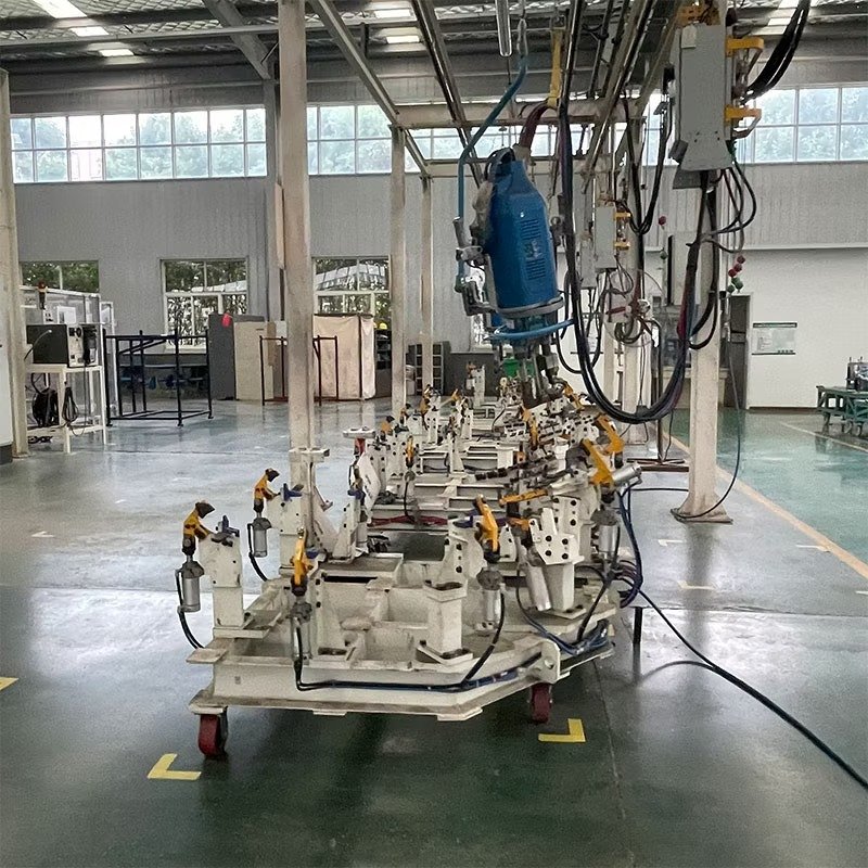
The basic structure of the fixture: The fixture consists of a table, a support, an L- plate, a reference pin, a reference surface, a clamping mechanism (cylinder, a clamping arm, a U- shaped limit block), etc.
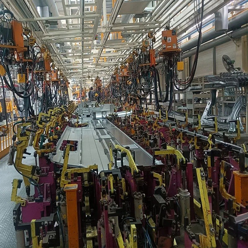
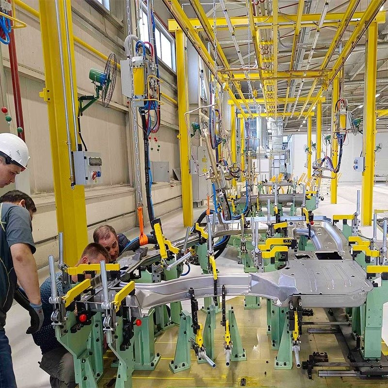
The role of the welding fixture in car body production is to install the workpiece (stamping part or assembly part) to the position set by the process and tighten it through the coordinated action of the positioning pins (reference pins), S -face blocks (reference surfaces), clamping arms and other components on the fixture to prevent the workpiece from moving and displacement, thereby ensuring the consistency and stability of the car body welding accuracy.
Check fixture skeleton and split body: 1) Resin: Resin with good surface and wear resistance, reinforced with glass fiber to give it sufficient strength. 2) Steel.
Gauge frame reinforcement structure: After the steel pipe structure is completed, proper heat treatment should be carried out to eliminate internal stress. The gauge structure should have sufficient strength and should not produce any warping deformation under normal use.
1) The parts of the finished product that require precision and the method of confirming the precision
2) Importance of accuracy requirements
3) Consider the deformation of the finished product during stamping
4) It should be easy to use, easy to make, and cost-effective
5) The overall structure is solid and not easy to deform
1) Familiar with digital model and product technology
2) Determine the design of the inspection fixture
3) The design is presented in the form of a sketch, including the following information: positioning method, hole location, boundary detection method ( cutting or drawing ), clamping jaws, and the general location of the positioning surface
4) After review, 3D modeling of the inspection fixture is carried out : the surface structure and functional parts are arranged according to the information provided by the digital model.
5) Output detailed design drawings and 3Dmodels
6) Arrangement of positioning device
Different positioning methods are used according to the size of the part. When there are more than 2 holes, pin positioning is used. When there is 1 hole, pin positioning and zero-face positioning are used. When there is no hole, face positioning is used. The clamping device can use standard jaws or strong magnets.
In short, the design of the inspection fixture must be based on the familiarity with the stamping process. The offset curved surface is the benchmark for CNC machining. For very complex stamping parts , when the digital model cannot be offset, a three-coordinate measuring instrument is used to reverse scan the points and pave the surface to obtain the morphological surface.
1) Qualified accuracy
2) The structure of the inspection fixture is reasonable
3) Material selection meets requirements
4) Painting complies with the specifications
5) Clear signs and markings
6) Complete additional documents
| Measurement Surface/Item | Tolerance Range/Requirement |
|---|---|
| Part shape and functional measurement surface (5mm gap, base plate parallelism) | 0.1/1000 |
| Surface | ±0.1 |
| Base plane parallelism, perpendicularity | ±0.5/1000 |
| All molded surfaces (non-measurement surfaces) | ±0.2, 0.05/1000 (Note: There may be two different tolerance requirements here, which need to be confirmed based on specific circumstances) |
| Inspection pin hole position | ±0.05 |
| Base hole position | ±0.05 |
| Scribing hole position | ±0.15 |
| Relative positional error between base holes | 0.03 |
| RPS positioning hole and pin position | ±0.05 |
| Scribing hole diameter | ±0.2 |
| RPS surface, support surface | +0.10 |
| Visual hole position | ±0.2 |
| Curved measurement surface | ±0.15 |
| Visual hole diameter | ±0.2 |
| Part outer contour measurement surface (flush surface) or line | ±0.1, 0.1/1000 (Note: There may be different tolerance requirements for different measurement surfaces or lines here) |
| Grid line position error relative to the datum | 0.1/1000 |
| Shape gauge or caliper gauge | ±0.15 |
The inspection and acceptance of the inspection tools include the inspection of accuracy, the review of appearance and operability, and the inspection and acceptance of additional documents and packaging.
1) Accuracy detection
2) Appearance and operability inspection
3) Acceptance of additional documents
1) Portable 3D coordinate measuring machine inspection
2) Gantry type 3D coordinate measuring machine inspection
3) Manual three-coordinate detection
1) Keep the table clean, free of welding slag, oil stains, dust, shunt burns or impact marks, the coordinate scale lines are clear and complete, and the tapping operation is carried out on the table strictly.
2) Regularly check the support and tighten the connecting bolts and screw locking nuts, and regularly check and adjust the levelness of the table.
3) Regularly check the tightened bolts of the L -plate (it is best to mark them with a marker), and regularly check whether the positioning pins are loose or fall off.
4) Check the reference surface regularlyTighten the connecting bolts (it is best to mark with a marker), and regularly check whether the positioning pins are loose or falling off; keep the surface clean, without shunt burns, bumps, and welding slag dirt; the gap with the workpiece in the clamped state is less than 0.1mm .
5) Reference pin
① There are no shunt burn marks and no welding slag dirt on the surface of the reference pin.
②The movable pin guide part should be well lubricated.
③ Carry out daily and regular inspections on the wear and assembly conditions of the positioning pins;
6) Clamping mechanism
①. The convex and concave components of the U -shaped limit block should be tightened reliably without looseness, and the welding slag and dust should be attached to the stop surface; under the tightening condition, the convex and concave components of the clamping arm (or swing arm) should not be displaced relative to each other when pushed by hand ( if there is dislocation, the matching clearance between the stop surfaces must be further checked (with a feeler gauge). If the clearance is ≥ 0.1mm , it should be replaced. )
② During the operation, try to avoid collision between the welding gun (or workpiece) and the clamp to avoid deformation of the clamp arm; avoid direct contact between the welding gun and the clamp assembly to avoid shunt burns to the clamp assembly; no welding slag should be attached to the surface of the clamp; the connecting bolts of each part of the clamp arm should be tightened reliably, and the hinge pin should be well lubricated; daily inspections should be carried out to check the clamping condition of the clamp arm. In the clamped condition, use your hand to move the clamp arm from the top and bottom and left and right directions. If there is any looseness, further check the condition of other components of the clamping mechanism to ensure the reliability of the clamp.
7) Pneumatic triplex
During daily inspection, check the bottom of the cup to see if there is any liquid or sediment (dust) accumulated. Drain the accumulated material in the filter cup at any time. Blockage of the filter element will cause pressure drop. The filter element should be regularly disassembled and cleaned before replacement to keep the inside and outside of the cup transparent and clear (Note: the compressed air source must be turned off when disassembling and cleaning the filter cup).
The working pressure of the fixture air circuit cannot be adjusted at will, the pressure reducing valve adjustment hand wheel should be in a locked state; the pressure gauge should be sensitive and accurate.
The oil mist device must use special gas lubricating oil: the oil output must be adjusted appropriately. Too much oil output will not only cause waste, but also pollute the environment. Too little oil output will cause poor lubrication and damage the equipment. Generally, the cylinder is required to produce one drop of oil every 30±5 movements . Clean and maintain regularly to keep the inside and outside of the cup clean and transparent, the scale clear, and no oil stains attached. Refill oil in time to ensure that the oil level in the cup is above the lower scale line.
8) Manually operated valve
The button should be easy to operate, reset quickly and completely, and there should be no air leakage.
9) Travel valve
The mounting bolts of the travel valve and cam must be tightened securely without any looseness; when the cam travel presses the roller lever, the valve must be fully opened without being pressed too hard; when disengaging, it must be complete and thorough, not half-detached; the valve stem must be reset sensitively and in place.
10) Cylinder
During the operation, avoid collision and diversion between the welding gun (or workpiece) and the cylinder and accessories; there should be no leakage or gas blowby in the cylinder, otherwise it will not be clamped tightly or added in place; the locking nuts of the throttle valve and buffer valve on the cylinder should be tightened securely; the compressed air must be clean and contain sufficient lubricating oil mist to ensure good lubrication of the cylinder.
11) Throttle valve
After the throttle valve is properly installed and debugged, the locking nut must be tightened. Daily inspection must be carried out to check the tightening and readjust it when necessary to avoid collision between the welding clamp (or workpiece) and the valve body.
1) Weld gauge : Compare weld height and weld leg size through standardized templates (such as ISO 17637 standard), with a typical accuracy of ±0.1mm
2) Contour detector : It uses a contact probe to measure the surface roughness of the weld, and can detect defects such as undercut and collapse.
3) Welding shrinkage compensator : predicts welding deformation based on the material thermal expansion coefficient and is used for tooling design compensation.
1) Laser profile scanner : uses the principle of triangulation to reconstruct the three-dimensional shape of the weld with a resolution of 0.01mm (such as Keyence LJ-V7000 series)
2) Industrial CT detection : X-ray tomography is used to detect internal pores, unfused and other defects, with a detection sensitivity of ≤Φ0.3mm
3) Ultrasonic phased array (PAUT) : Multi-chip array realizes full-section scanning of welds and can identify 0.5mm level defects in depth
1) Machine vision system : Weld defect classification based on deep learning algorithms (such as YOLOv5), with recognition speed ≤50ms/frame
2) Online monitoring device : Integrates arc sensing, spectral analysis and other technologies to monitor welding penetration and heat input parameters in real time
3) Digital twin detection platform : Predict welding deformation through virtual simulation, with an error of ≤3% compared with physical detection data
| Industry | Typical test objects | Key test parameters | Technical Standards |
|---|---|---|---|
| Automotive | Body in white spot welding/laser welding | Welding spot diameter ≥4mm Welding core strength ≥800N | ISO 14273 VW 01103 |
| Aerospace | Titanium Alloy Electron Beam Welding | Porosity ≤ 0.5% Melting depth deviation ± 0.2mm | AMS 2680 NAS 410 |
| Energy Equipment | Pipe girth weld | Misalignment ≤1.5mm Residual height 0-3mm | ASME B31.3 API 1104 |
| Rail Transit | Aluminum alloy body MIG welding | Undercut depth ≤ 0.5mm Welding seam width 8±1mm | EN 15085 DIN 6700 |
1) Multi-sensor fusion detection uses laser-vision-ultrasound composite detection technology (such as Eddyfi Mantis) to achieve simultaneous detection of surface and internal defects, improving detection efficiency by 40% and reducing the missed detection rate to below 0.1%.
2) Adaptive environmental compensation technology Intelligent gauges equipped with temperature/humidity compensation modules (such as Hexagon Absolute Arm) can maintain a measurement accuracy of ±15μm/m under working conditions of -20℃ to 50℃.
3) Digital measuring tools replace traditional gauges. The virtual measuring tool system based on MBD model (such as 3DCS Variation Analyst) automatically generates GD&T reports through digital-to-analog comparison, shortening the inspection cycle by 70%.
| Check fixture type | Accuracy range | Detection speed | Applicable scenarios |
|---|---|---|---|
| Contact type three coordinates | ±1.5μm+L/250 | 500mm/s | Laboratory precision testing |
| Laser Tracker | ±15μm+5μm/m | Real-time measurement | Large-scale on-site inspection |
| Industrial DR System | 2% contrast sensitivity | 30m/min | Pipeline weld inspection |
| AI Vision System | Defect recognition rate ≥99% | 60fps | Production line online inspection |
The technological development of welding gauges is evolving towards high precision, intelligence and systematization . From traditional manual measuring tools to intelligent detection systems based on digital twins, their technical connotations have gone beyond the scope of simple quality control tools and have become an indispensable quality data center in intelligent manufacturing systems . In the future, with the breakthrough of new technologies such as quantum sensing and terahertz detection, welding detection will achieve full-dimensional coverage from macro to micro, from offline to online, providing core quality assurance for the high-quality development of the manufacturing industry.